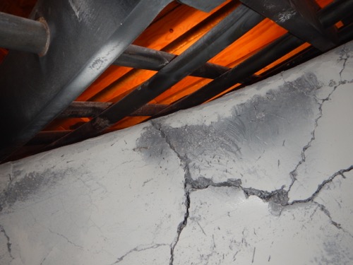
Frequently, on a turnaround of a Fluid Catalytic Cracking (FCC) unit, refractory linings in the major vessels and transfer lines are found to have sustained significant damage. Repairs are time consuming, and can be difficult to effect, for example in catalyst transfer lines, reactor riser, or reactor overhead vapor line to the main fractionator.
These refractory failures occur for various reasons, one of which is obviously age of the linings. However, one of the major factors impacting refractory failures is exposure to the thermal cycle which occurs when a unit has a feed outage, and certainly the inevitable thermal cycle associated with a full unit shutdown, such as for turnaround. Although these great changes in temperature in the unit cannot generally be avoided, there are some steps and precautions that can be taken to minimize damage to refractory linings.
Rate of temperature change is critical.
One of the most important precautions that can be adopted is to control, where possible, the rate of change of temperature of the linings. Refractories do have a coefficient of expansion, but that expansion is usually quite slow due to the thermal insulating properties of the refractory. Many refractory specialists specify controlling the rate of temperature increase or decrease to a maximum of 200°F (110°C) per hour.
During a unit startup, when the initial heatup is usually with blower air through an air heater, it is fairly easy to achieve this heatup rate and thus protect the regenerator vessel and flue gas line refractories. Controlling the temperature in the feed riser during initial transfer of catalyst from the regenerator is, however, more difficult, and requires close attention, and it must be stated, patience on the part of the operator. The required slow transfer is achieved by careful and slow opening of the regenerated catalyst slide valve. The process is made easier if the catalyst temperature in the regenerator at this time is maintained relatively low, for example, 1000°F (538°C). Also, minimizing pressure differential between regenerator and reactor to that which is just sufficient for catalyst transfer, reduces the driving force for that transfer.
Where possible, the rate of temperature change of the refractory linings during unit cooldown should also be controlled to the recommended rate.
In addition, procedures can be adopted to minimize the severity of a temperature cycle. For example, on an unplanned feed outage, when catalyst circulation is also stopped, restoration of some catalyst circulation, where possible, will prevent a large drop in reactor-side temperatures, and avoid a complete thermal cycle from operating temperature to steam temperature.
It should be noted that this guideline for maximum rate of temperature change applies only to refractories that have already been dried out, or cured, or that have already been exposed to normal unit operating temperatures. The guideline is different for fresh refractories that require a temperature drying procedure, and a special procedure is usually specified by the refractory installer or local refractory specialist. Obviously, those refractories that are chemically-curing do not require a formal temperature dryout procedure.
Failure can be caused by explosive spalling due to wet refractory
During a unit startup in particular, the riser/reactor side of the unit is steamed for extensive periods of time, to purge out air in preparation for eventual introduction of feed. During this steam-out step, the quality of steam used is of some importance. The higher the temperature (degree of superheat), the better for avoiding condensation of liquid water. However, no degree of steam quality can ensure that some water will not form deep within thick refractory linings, such as those on reactor vessel walls.
The following model can be visualized: The temperature of the inner surface of the lining will be essentially the same as that of the steam. Halfway deep in the lining, the temperature will obviously be much lower. This temperature gradient progresses, with the temperature being lower with increasing depth. Eventually, at some depth, that temperature will be at the steam condensation point, since at the vessel wall the temperature is close to skin temperature, which is close to ambient. Since refractories always have some porosity, steam does permeate throughout the depth of the lining. Thus, liquid water can be present. Now, if the heatup rate is excessively rapid, that water may be vaporized rapidly, but cannot escape back through the lining into the vessel. Explosive spalling can therefore be the result.
Thus, the key to protecting refractory linings in an FCC unit is the close control of heatup and cooldown rates, where this can possibly be done.
One response to “Protecting Refractory Linings in FCC Units”
Leave a Reply
You must be logged in to post a comment.


Thermal shock can indeed also cause ‘biscuiting’ in the HexMetal structure in addition to weld breakage due to expansion and contraction.
This causes the flow to become turbulent and the cyclones do not perform as they should. Catalyst loss can be reduced by using the SpeedHex3® system allowing the whole lining to wear to the bare min thickness and thus offer greater efficiency. The system has been on the market for 5 years with great success. Additionally corrosion and cokes build up from the back of the lining is a thing of the past.